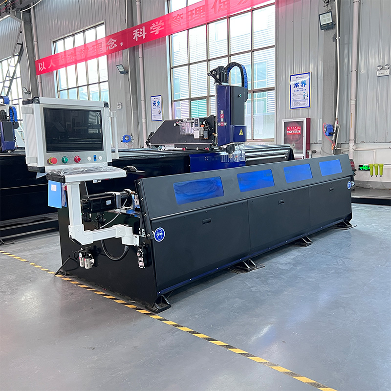
The transition from isolated cutting stations to integrated multi-function centers is critical for high-volume aluminum fabrication. Modern manufacturing simply demands continuous workflow evolution. Relying on legacy methods severely hinders your competitive edge. Separating milling, drilling, and cutting processes introduces severe handling bottlenecks. This manual transfer between stages actively encourages tolerance stacking. These inefficiencies heavily increase labor costs, particularly in demanding architectural and industrial extrusion workflows. Evaluating the right equipment requires moving beyond basic spec sheets. We must analyze its practical impact on workflow consolidation. You will soon learn how CAM integration and overall equipment effectiveness define your true production success. Implementing unified systems radically alters your baseline productivity. Isolated machines cannot match the synchronized output of an all-in-one center. We must recognize fragmented production as a direct threat to throughput. Every time operators move parts, they introduce potential human error. A consolidated approach eliminates these costly touchpoints. Today, surviving in aluminum fabrication means embracing multi-process centers. You will discover exactly how these machines handle rigorous demands. We evaluate spindle rigidity, multi-axis capabilities, and software compatibility. By the end, you will know how to construct a truly scalable processing line.
Key Takeaways
Consolidating drilling and milling reduces part handling and minimizes clamping errors inherent in multi-machine workflows.
Maximum ROI depends heavily on your facility's CAM software readiness and post-processor compatibility.
While highly effective as an aluminum window door CNC machine, evaluating maximum profile lengths and chip evacuation systems is necessary to confirm fit for your specific extrusions.
True workflow acceleration requires pairing the machine with standardized workholding and automated material feeding where applicable.
The Cost of Fragmented Processing in Aluminum Fabrication
Framing the Business Problem
Moving extrusions between multiple standalone machines creates massive invisible expenses. You might utilize a dedicated CNC aluminum cutting machine for raw sizing. After cutting, operators manually transport these lengths to separate drilling or routing stations. This fragmented workflow guarantees lost production hours. Parts sit idle in carts waiting for the next available spindle. Managing work-in-progress inventory becomes incredibly difficult. You essentially pay your staff to move metal rather than machine it. Quantifying these hidden handling costs reveals the true financial drain of disconnected floor layouts.
The Threat of Tolerance Stacking
Precision is everything when fabricating complex architectural profiles. Multiple clamping and unclamping cycles actively degrade final part precision. Every time an operator loads a profile into a new machine, slight alignment errors occur. A misaligned hole on a secondary operation compromises the entire extrusion. These minor deviations multiply across different machines. We call this phenomenon tolerance stacking. Over time, it leads to rejected parts and frustrating assembly issues downstream. An integrated machine clamps the part once. It then performs all necessary operations relative to a single, secure datum point.
Floor Space and Labor Reallocation
Maintaining separate equipment drains your capital and operational resources. Dedicated saws, standalone routers, and drill presses consume massive amounts of floor space. Adopting a unified Aluminum Profile Processing Machine condenses your footprint footprint significantly. This consolidation allows you to rethink your entire facility layout. Labor expenses also drop sharply. You no longer need three operators tending three different machines. One trained technician can manage the entire consolidated workflow. You can then reallocate redundant staff to more valuable assembly or quality control tasks.
Common Mistake: Facility managers often calculate machine footprint based solely on the equipment dimensions. They forget to account for the necessary staging areas between multiple standalone machines.
Defining Success Criteria
Integrating a multi-function center must yield measurable results. A successful implementation should reduce overall cycle times by at least 30%. The equipment must also maintain or exceed your current dimensional accuracy standards. You need verifiable data proving the machine handles your toughest profiles. Success means your operators spend less time loading and more time cutting. It means scrap rates drop because parts undergo fewer handling cycles. These metrics dictate whether the integration actually improves your shop floor efficiency.
Evaluating the A9 Aluminum Milling and Drilling Machine: Core Capabilities
Feature-to-Outcome Mapping
Understanding a machine requires mapping its physical features to your actual production outcomes. Spindle speed and structural rigidity dictate cut quality. The A9 Aluminum Milling and Drilling Machine tackles specific chip loads without severe tool deflection. It handles structural aluminum efficiently because the gantry framework absorbs heavy vibrations. Furthermore, we must evaluate its multi-axis operations. Processing multiple faces of an extrusion in a single setup drastically cuts handling time. The spindle articulates to reach top, front, and back surfaces without operator intervention.
Hardware Feature | Operational Outcome | Workflow Benefit |
High-Torque Spindle | Maintains RPM during heavy chip loads | Prevents tool stalling in thick-walled extrusions |
Multi-Axis Articulation | Machines 3+ faces in one setup | Eliminates manual part repositioning |
Heavy-Duty Gantry | Reduces micro-vibrations | Improves surface finish and extends tool life |
Cycle Time Reduction
Speed depends on more than just aggressive cutting feeds. We analyze rapid traverse rates between different hole locations. Fast non-cutting movements shave minutes off complex profiles. Automatic tool change (ATC) speeds also play a massive role.
Rapid Traverse: Quicker movement from one end of a 6-meter profile to the other.
ATC Integration: Swapping a drill bit for an endmill in seconds rather than minutes.
Spindle Ramp-Up: Reaching optimal RPM faster after a tool change.
These combined micro-efficiencies generate massive time savings across an entire production shift.
Material Handling and Clamping
Securing thin-walled extrusions presents a unique engineering challenge. Aggressive clamping crushes delicate architectural profiles. Loose clamping allows vibration and ruins part dimensions. The integrated clamping system must adapt to varying cross-sections dynamically. It uses distributed pneumatic pressure to secure profiles firmly. This prevents warping while maintaining enough grip for heavy milling passes. You must verify the clamps can shift automatically to avoid the spindle path during machining.
Best Practice: Always perform a dry run using soft jaws or 3D-printed custom pads when gripping highly polished or anodized extrusions.
Component Durability
Continuous heavy-chip environments destroy weak machinery. We must review the expected lifespan of vital components. Linear guideways require constant lubrication to resist aluminum dust ingress. Ball screws face immense axial loads during rapid directional changes. Industrial-grade seals and wipers protect these moving parts from abrasive contamination. Durable components ensure the machine runs accurately for years, rather than months.
![A9 Aluminum Milling and Drilling Machine Integration]()
CAM Preparation and Software Integration Realities
The Software Bottleneck
Incredible hardware means nothing if you cannot program it efficiently. The software bottleneck destroys production schedules daily. Engineering teams must generate code quickly to keep the spindle turning. Complex multi-face machining requires advanced toolpath generation. If your software lacks intuitive profile recognition, your programmers will struggle. They will spend hours manually selecting boundaries instead of automating the workflow. A powerful CNC Aluminum Milling Machine requires equally robust software to achieve maximum throughput.
Post-Processor Compatibility
Code translation dictates machine behavior. Standard CAD/CAM environments like Fusion 360 or Mastercam output generic coordinate data. A post-processor translates this data into the specific G-code your machine controller understands. Ensuring seamless translation is absolutely mandatory. A generic post-processor might crash the machine by ignoring custom clamp avoidance routines. You must work closely with the machine vendor to validate the post-processor before cutting real parts. It must handle specialized macros, tool length offsets, and multi-axis indexing perfectly.
Setup & Simulation
Digital verification saves expensive hardware. Utilizing digital twins allows programmers to verify toolpaths safely on a computer screen. This process prevents catastrophic collisions between the spindle and the pneumatic clamps. Simulation visualizes material removal rates and highlights potential gouges.
Confirm clamp positions relative to toolpaths.
Verify tool length stick-out prevents holder collisions.
Optimize rapid moves to avoid unnecessary Z-axis retracts.
Check over-travel limits on exceptionally long extrusions.
Operator Adoption
Floor staff often resist complex new technology. Managing a multi-function center differs vastly from operating legacy single-action saws. Operators need comprehensive training on the new control interface. They must understand how to recover from tool breakage safely. Training should cover alarm diagnostics, basic preventive maintenance, and fixture alignment. Gradual introduction builds operator confidence. Pair your best technicians with the manufacturer's application engineers during the initial installation phase.
Workflow Integration: Building a Scalable Processing Line
Upstream and Downstream Synergies
A unified machine must bridge the gap between material storage and final assembly. Think about how raw stock reaches the machine. Automated racking systems can feed profiles directly onto the loading table. After processing, the finished parts must move smoothly to deburring or hardware insertion stations. The A9 fits perfectly into this continuous flow model. It eliminates the chaotic staging carts typically scattered across a shop floor. Synchronizing material delivery with machine cycle times ensures the spindle never starves for work.
Window and Door Applications
Architectural fabrication relies heavily on specialized routing. When utilized as a dedicated aluminum window door CNC machine, performance metrics become highly specific. The spindle must process lock holes, complex hinge slots, and intricate weep holes rapidly. Plunge milling through thick thermal breaks requires distinct tool geometries. The machine excels here because it indexes the profile to hit multiple faces instantly. Precision routing guarantees weather seals fit perfectly during final assembly.
Automation Potential
True continuous production demands automation. We assess the feasibility of integrating automated bar feeders. These systems push raw lengths into the machining zone without human effort. Robotic offloading systems present another massive opportunity. An articulating arm can grab finished segments and stack them onto shipping pallets. Pairing an Aluminum milling and drilling machine with automated handling removes the operator bottleneck entirely. Lights-out manufacturing becomes a realistic goal for high-volume extrusion runs.
Integration Level | Material Feeding | Part Offloading |
Manual Workflow | Operator loads 6m lengths manually | Operator unclamps and carts away parts |
Semi-Automated | Pneumatic pop-up rollers assist loading | Conveyor belt moves scrap to bins |
Fully Automated | Inline bar feeder pushes stock continuously | Robotic arm palletizes finished segments |
Standardization
Rapid changeovers depend on strict standardization. Developing standardized fixturing protocols minimizes downtime between different profile geometries. Use modular clamping pads that snap into place without tools. Document specific jaw pressures for varying wall thicknesses. When operators follow standardized setup sheets, changeover times drop from hours to minutes. Consistency ensures the first part out of a new batch matches the final part of the previous run.
Operational Limitations and Implementation Risks
Transparent Assumptions
Machines never operate in a vacuum. The equipment requires stable three-phase power to prevent spindle faults. You must supply specific compressed air volumes to drive the pneumatic clamping systems reliably. Moisture in your air lines will destroy internal solenoid valves quickly. Dedicated dust and chip extraction is absolutely vital. Standard shop vacs cannot handle the volume of chips generated. You must install industrial extraction units to keep the linear rails clean and function at stated capacities.
Capacity Constraints
Every machine has physical limits. We must define the maximum length and cross-sectional area it can process safely. While the bed might hold a six-meter profile, the actual Y and Z axis stroke determines what you can reach. Processing oversized profiles often requires complex repositioning. Custom workarounds, like indexing the part mid-program, increase cycle times and introduce error. You must verify your thickest, most complex profiles fit entirely within the standard machining envelope.
Chip Evacuation Challenges
Aluminum machining generates massive volumes of stringy chips. The physical reality of managing this waste is daunting. Chips pack tightly into tight extrusion pockets. This prevents coolants from reaching the cutting edge. Evaluating the risk of coolant contamination is critical. If chips accumulate around the spindle, you risk dangerous chip recutting. Recutting instantly dulls expensive endmills and ruins surface finishes. Ensure the machine features angled bed designs and high-pressure flood or mist coolants to flush chips away effectively.
Common Mistake: Ignoring chip accumulation inside hollow extrusions. Always program a brief air-blast sequence to clear internal chambers before unclamping the part.
Maintenance Realities
High-performance machinery demands rigorous upkeep. Assessing the required preventative maintenance schedule is non-negotiable. Spindle chillers need fluid changes. ATC carousels require regular alignment checks. You must evaluate the availability of replacement parts from the vendor. A blown servo drive could halt your line for weeks if parts sit overseas. Review the vendor support SLAs carefully. Guarantee they offer remote diagnostic support to troubleshoot minor software faults instantly.
Conclusion
Evaluating this integration requires a hard look at your current floor inefficiencies. The machine stands out as a highly viable candidate for facilities seeking to eliminate secondary processing bottlenecks. However, realizing its full potential demands a mature software infrastructure and proper post-processor alignment. It offers substantial efficiency gains for continuous profile workflows, provided you respect its physical capacity limits.
Next-step actions for your engineering team:
Request a physical test cut from the manufacturer using your thickest, most complex aluminum profile.
Audit your current CAM software’s post-processor library for multi-axis extrusion routing compatibility.
Assess your facility's compressed air and chip extraction systems against the machine's required specifications.
FAQ
Q: What are the maximum profile dimensions the A9 can handle without repositioning?
A: Maximum dimensions depend entirely on the specified X, Y, and Z workable stroke limits of the exact model variant. Typically, the Z-height dictates the maximum cross-section. Processing oversized profiles requires specialized index-and-reclamp routines. These routines shift the material along the X-axis, allowing the machine to process lengths exceeding the standard bed size safely.
Q: Can this replace a dedicated CNC aluminum cutting machine entirely?
A: While it effectively combines operations, it rarely replaces high-volume bulk cross-cutting entirely. If your workflow requires thousands of straight sizing cuts daily, a dedicated dual-head saw remains faster. The multi-function center excels when combining cuts with complex milling, drilling, and slotting on a single complex extrusion.
Q: What CAM software is recommended for this aluminum milling and drilling machine?
A: Industry-standard software like Fusion 360, Mastercam, and SolidCAM works perfectly. The critical factor is not just the software, but utilizing a validated post-processor. A proven post-processor ensures the machine interprets multi-face machining features safely, automatically avoiding clamps and preventing dangerous spindle collisions.
Q: Does the machine support rigid tapping for industrial profiles?
A: Yes, it supports rigid tapping provided the spindle is equipped with a high-resolution encoder. This encoder synchronizes spindle rotation with Z-axis feed rates perfectly. The machine generates sufficient torque at lower RPMs, which is necessary to form clean, accurate threads in thick structural aluminum profiles without snapping taps.