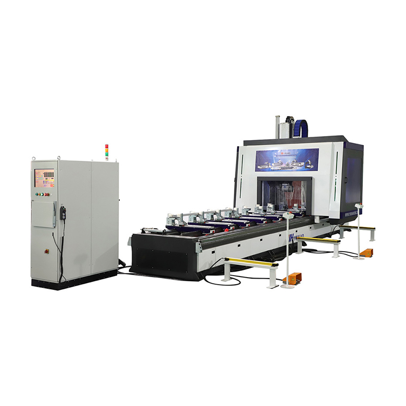
Upgrading to a CNC-driven hardware setup is a high-stakes capital expense. Buyers constantly navigate complex manufacturer spec sheets. These documents often blur the lines between theoretical capabilities and actual shop-floor performance. You need clarity to make the right investment. This article strips away confusing marketing jargon. We provide a straightforward, vendor-agnostic evaluation framework. Our guide covers essential machine configurations, tooling constraints, software integration, and common implementation risks. We help ensure your hardware investment aligns perfectly against your exact production volume. You will understand how to match tolerances to your actual daily needs. Making a poorly matched purchase leads to severe production bottlenecks. Conversely, the right equipment drastically reduces scrap and operator fatigue. We explore crucial distinctions between various axis setups. You will learn to identify hidden facility costs. You will also discover why software ecosystems matter more than raw machine speed. Let us dive into the core realities of modern extrusion processing.
Key Takeaways
Hardware specifications (spindle speed, torque, linear guides) must match specific extrusion profiles; over-specifying leads to wasted capital, while under-specifying causes tool deflection and scrap.
The leap from 3-axis to a 4 axis CNC aluminum profile machining center or 5-axis system should be justified by the need for complex, multi-face machining without manual part repositioning.
Software ecosystem compatibility (CAD/CAM integration) is frequently a more significant bottleneck to actual throughput than machine cycle times.
Effective chip evacuation and mist lubrication are non-negotiable for aluminum to prevent tool welding and ensure surface finish quality.
Defining the Production Bottleneck: When to Upgrade
Understanding exactly when to invest requires a hard look at your current shop floor. You must identify specific operational triggers before committing capital. Waiting too long creates delivery delays, while buying too early strains cash flow. We see three primary success criteria justifying an automated equipment upgrade.
Success Criteria for Investment
High Scrap Rates: Manual layout routines rely heavily on tape measures and center punches. Human operators naturally make errors during long shifts. This fatigue causes dimensional inaccuracies. Parts fail quality control inspections and end up in the scrap bin.
Throughput Limitations: Traditional machinery forces operators to unclamp, manually rotate, and re-clamp heavy extrusions for multi-face processing. You lose massive amounts of time during these handling phases. The actual cutting time becomes secondary to part handling time.
Labor Dependencies: Finding highly skilled machinists gets harder every year. Relying on master tradespeople for repetitive, standard operations wastes their talent. Automated setups let you assign complex programming to your best staff while junior operators handle machine loading.
Evaluating ROI
Calculating the true return on investment requires looking far beyond the initial sticker price. You must analyze the total operational footprint. Assess your current floor space accurately. These large machines require significant clearance for safe material loading. You also need to factor in facility power upgrades. Industrial equipment often demands 3-phase, high-amperage electrical drops. Check your existing pneumatic supply lines as well. Upgrading air compressors to maintain consistent clamping pressure adds hidden expenses. Finally, include comprehensive operator training time in your budgetary projections. Lost production during the learning curve impacts your first-quarter profitability directly.
Axis Configurations and Capability Mapping
Selecting the right axis configuration dictates your entire production flow. Over-purchasing capabilities wastes money. Under-purchasing creates frustrating workflow bottlenecks. Let us break down the physical realities of each machine type.
3-Axis Systems
A standard 3-axis configuration works best for single-face operations. The spindle points downward and moves across the X, Y, and Z planes. These machines offer incredible structural rigidity. They also present the lowest entry cost. If your product mix consists mostly of simple structural framing, this setup performs flawlessly. Operators learn the software quickly. Maintenance remains highly predictable.
4-Axis Capabilities
Stepping up to a 4 axis CNC aluminum profile machining center unlocks massive throughput gains. The spindle rotates mechanically. You can process three sides—the top, front, and back—using a single clamping setup. The machine executes multiple operations without asking the operator to touch the material.
This configuration serves as the undisputed industry standard for high-volume architectural extrusions. Industrial profiles requiring multi-face tapping also benefit immensely. Cycle time reduction remains the primary driver here. You eliminate the human errors associated with manual part rotation.
5-Axis Capabilities
The premium tier involves fully interpolating movement. A 5 axis aluminum profile milling and drilling machine manages complex spatial angles simultaneously. The cutting tool navigates around obstacles seamlessly. You can execute custom cutouts and highly specialized routing paths.
Complex curtain walls require these capabilities. Aerospace components and highly customized facades demand absolute spatial freedom. However, you should maintain healthy skepticism during procurement. Upfront costs run significantly higher than simpler models. You must also manage complex CAM programming software. Buying this technology proves completely overkill for standard 90-degree framing.
Industry-Specific Requirements: Architectural vs. Industrial
Machining delicate window frames requires entirely different engineering than plowing through solid industrial T-slots. You must align the hardware engineering to your raw material properties. A single machine rarely excels at both tasks equally.
Architectural Window and Door Processing
Processing a typical aluminum profile CNC machine for window and door machining focuses heavily on spindle speed over raw torque. High speeds ranging from 18,000 to 24,000 RPM remain strictly necessary. Fast rotation ensures clean, burr-free routing for lock holes, drainage slots, and delicate hinge placements. Thinner-walled profiles warp easily under heavy cutting pressure.
Clamping needs change drastically here. Pneumatic clamps must secure the part firmly. They must accomplish this without crushing the internal webs. More importantly, the clamping pads cannot mar expensive powder-coated or anodized finishes. Surface scratches immediately ruin architectural products.
Industrial Extrusions (4080/8080 T-Slot Profiles)
Heavy industrial framing flips the engineering requirements upside down. Drilling a 20mm through-hole into an 8080 profile requires massive force. You need higher torque at lower RPMs. Tapping thick aluminum webs will instantly stall a weak, high-speed router spindle. Tool deflection becomes a serious risk. When a drill bit bends, hole tolerances drift drastically.
Rigidity becomes the primary focus. Heavy-duty cast iron beds absorb intense vibration during high-load milling. Reinforced steel frames prevent the machine chassis from twisting. If the frame flexes, your precision disappears.
Machining Requirements Comparison
Requirement Category
Architectural Profiles
Industrial Extrusions
Spindle Focus
High Speed (18k-24k RPM)
High Torque (Low-Mid RPM)
Primary Operations
Routing, light slotting, weep holes
Deep drilling, rigid tapping, heavy milling
Clamping Priority
Surface protection, non-marring
Maximum grip force, crush resistance
Chassis Rigidity
Standard steel frame sufficient
Heavy cast iron or reinforced steel required
Core Evaluation Criteria for Shortlisting Vendors
Separating marketing hype from mechanical reality takes diligence. When you invite vendors to quote an automatic aluminum profile machining center, you must mandate clear specifications. Focus on four core mechanical pillars.
Spindle and Drive Technology: Evaluate continuous power ratings rather than peak power claims. Manufacturers love highlighting peak horsepower. Continuous power dictates your daily milling capacity. Look for reputable servo motors from trusted brands like Yaskawa or Siemens. Choose direct-drive spindles over belt-driven units. Belts stretch and introduce mechanical backlash over time. Direct drives offer superior precision and greatly extended longevity.
Guideways and Motion Control: Insist strictly on linear ball or roller guideways for the X, Y, and Z axes. Brands like THK or HIWIN set the global quality benchmark. Inferior guideways wear unevenly. Premium linear rails ensure long-term positional accuracy, typically holding ±0.1mm/m across years of heavy shifts.
Tool Management: Evaluate the Automatic Tool Changer (ATC) capacity carefully. Fast tool change speeds reduce non-cutting cycle times. A magazine holding 8 to 12 slots provides the ideal standard. It covers all necessary drills, taps, and end mills for continuous operation without manual intervention.
Control System and Software (HMI): Assess the openness of the CNC controller. Proprietary locked-down controllers trap you into expensive service contracts. Syntec or Siemens controllers offer widespread reliability. Verify seamless file import capabilities. The system must accept standard `.dxf` or `.step` files easily. Confirm direct compatibility against your existing CAD/CAM stack. Native integration tools like Orgadata or LogiKal save hundreds of programming hours annually.
Implementation Realities and Machining Risks
Bringing advanced technology onto the shop floor introduces distinct physical challenges. Aluminum behaves unpredictably under intense machining friction. You must engineer your environment to handle these realities.
The Aluminum Welding Effect
Soft metals melt quickly. Aluminum adheres strongly to cutting tools under intense frictional heat. This built-up edge destroys end mills rapidly. A reliable aluminium profile drilling and milling machine must combat this heat. Assess the Micro-Drop Lubrication (MQL) system closely. Proper mist coolant applications prevent tool welding. They ensure adequate tool life while leaving a mirror-like edge finish.
Chip Management
High-speed routing generates massive volumes of silver chips. These chips pile up fast. Poor machine designs trap debris inside moving parts. Evaluate the structural layout carefully. Look for slanted bed designs shedding debris naturally. Integrated chip conveyors save your operators from sweeping the enclosure manually every two hours.
Handling Real-World Tolerances
Raw extrusions rarely arrive perfectly straight. Metal cools unevenly during the extrusion process. Raw material bows along long lengths. Twists happen frequently. Your new equipment must feature intelligent probing systems. Touch probes map the exact material position. The controller then compensates mathematically for bowing before cutting begins. Without probing, your drilled holes will drift off-center.
Operator Adoption
Transitioning staff from manual chop saws to computerized routing requires significant upskilling. Do not underestimate software intimidation. Your best manual machinist might struggle learning coordinate geometry. Factor in a minimum of one to two weeks of vendor-led onsite training. Supervised test runs build necessary confidence. Rushing the training phase guarantees expensive machine crashes.
Conclusion
Upgrading your facility demands strict adherence to engineering realities. Do not default automatically to a complex 5-axis system. A highly rigid 3-axis or 4-axis machine fits 95% of typical product mixes perfectly. You should prioritize rigid pneumatic clamping, robust software integration, and highly reliable local vendor support over flashy brochure specifications.
Before releasing any purchase orders, take a proactive next step. Compile your five most common extrusion profiles. Include your absolute most difficult profiles as well. Document your required daily cycle times. Mandate your shortlisted vendors to run a physical time-study or live test-cut on your specific files. Seeing your actual parts machined successfully remains the only true proof of capability.
FAQ
Q: What is the minimum spindle RPM required for clean aluminum routing?
A: For standard architectural profiles, 18,000 to 24,000 RPM is optimal. These speeds ensure clean, burr-free cuts when using single-flute carbide end mills. For heavier industrial drilling, continuous torque matters significantly more than peak RPM limits.
Q: Can these machines handle heavy industrial profiles like 4080 or 8080?
A: Yes, but standard window or door machines often lack the necessary Z-axis rigidity. You must specify your need to drill large diameters (e.g., 20mm holes) during the RFQ phase. This ensures the vendor quotes equipment featuring appropriate spindle torque and heavy structural mass.
Q: What CAD/CAM software is required?
A: Most modern machines accept standard G-code seamlessly. However, specialized hardware often uses macro-based proprietary software for easy parametric programming directly at the machine console. Many also integrate directly with industry-specific window software like LogiKal or SchüCal for automated file generation.
Q: Do I need a 4-axis or a 5-axis machine?
A: If you only need to machine the top, front, and back of a profile at standard 90-degree increments, a 4-axis machine works perfectly. A 5-axis setup becomes strictly necessary only for compound spatial angles, curved extrusions, or highly complex curtain wall joints.
Shandong Youhao Energy Technology Co., Ltd located in Rizhao E&D zone, is one leaderof CNC manufactures in wood-working machinery industry, which dedicates to the R&D.